How Does a CNC Machine Work?

A CNC machine turns digital instructions into controlled physical movement. CNC means computer numerical control. The machine reads coded commands, positions its axes, and removes or shapes material with a cutting tool. That sounds simple. It is not always simple.

CNC educator Mike Lynch describes the principle clearly: “A CNC machine follows programmed instructions to control cutting motion.” This statement captures the core of Cnc Machine Working, but practical machining demands more than code. Operators select cutting tools, set work offsets, secure the material, and check every critical dimension. A milling machine may move along three axes, while advanced equipment can rotate the workpiece during cutting. A small offset error can leave a visible step on an aluminum surface. Excessive speed may burn the tool or damage the finish. The machine cannot judge every mistake for itself.

This guide follows the process from design files to finished components. It explains coordinate systems, G-code, spindle speed, feed rate, tooling, and inspection. Real workshop experience matters here. A simulation may look perfect, yet the tool can still collide with a clamp. That uncomfortable gap deserves attention. Reliable Cnc Machine Working depends on accurate setup, maintained equipment, verified programs, and careful human judgment. The operator remains responsible. That point is easy to overlook.
How Does a CNC Machine Work?

CNC Machine Fundamentals: ISO 6983 G-Code and 3–5 Controlled Axes

How Does a CNC Machine Work?

CNC Machine Fundamentals: ISO 6983 G-Code and 3–5 Controlled Axes

A CNC machine follows digital instructions to remove material with measured, repeatable motion. That sounds simple. CAD geometry becomes a toolpath through CAM software. The controller then reads G-code and coordinates motors, spindle speed, feed rate, and coolant commands.

ISO 6983 provides a widely used structure for numerical-control programming. G00 commands rapid positioning, while G01 controls linear cutting movement. G02 and G03 create clockwise and counterclockwise arcs. M-codes manage machine functions, such as spindle start or program stop. However, controller interpretations can differ. I always check the machine manual instead of trusting familiar code.

Three axes use X, Y, and Z movement. X and Y usually position the cutter across the workpiece. Z controls cutting depth.

A five-axis machine adds two rotary axes, often A, B, or C. The tool can approach curved surfaces from changing angles. That reduces setups and may improve surface quality, but it increases collision risk and programming complexity.

Fortune Business Insights valued the global CNC machine market at about USD 83.3 billion in 2023. Its report projects continued growth through 2032, depending on market scope. Separately, the International Federation of Robotics reported 541,302 industrial robot installations in 2023. This wider automation figure shows the manufacturing shift, not CNC demand alone. A clean simulation can still miss a real clamp. Physical verification remains necessary.

CAD-to-CAM Programming: Toolpaths, Feed Rates, and Spindle Speeds in RPM

How Does a CNC Machine Work?

A CNC machine turns digital instructions into controlled cutting movements. The process begins in CAD, where I create the part’s geometry and define holes, pockets, or curved surfaces. CAM software then converts that model into toolpaths. These paths tell the cutter where to move, how deep to cut, and when to retract. A small mistake in the model can become a damaged workpiece.

Tool selection affects every programming decision. For example, a small end mill needs lighter cuts than a larger cutter. Feed rate controls how quickly the tool travels through material, while spindle speed controls rotation in revolutions per minute. A basic spindle-speed estimate uses RPM = cutting speed × 1000 ÷ tool diameter ÷ π. I still check the material, tool coating, machine rigidity, and coolant conditions.

Start conservatively.

During setup, I verify the work offset and tool length carefully. I also simulate the toolpath before machining, then run the first pass above the surface when possible. This reveals unexpected plunges, sharp direction changes, or insufficient clearance. Feed rates should not be copied blindly from a chart. Real machines behave differently, and my first setting is sometimes too cautious. Cutting sound, chip shape, and surface finish provide useful evidence. Thin, powdery chips may show poor engagement, while heavy vibration can signal excessive radial depth or spindle speed. Adjustments should be small and recorded for repeatable results.

Machine Setup: Workholding, Datum Zero, and ±0.01 mm Positioning

How Does a CNC Machine Work?

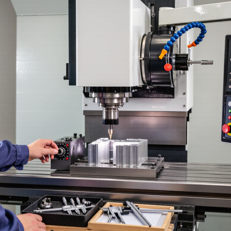
A CNC machine follows programmed coordinates to move cutting tools along controlled axes. Accurate cutting, however, begins before the program runs. The operator must secure the material without bending it or allowing vibration. A vise, fixture, or soft jaw should support the workpiece close to the cutting area. Excessive clamping force can distort thin stock. It feels stable, but the part may still move under load.

Workholding must also leave enough clearance for the tool, holder, and coolant flow. I check these areas by moving the machine slowly through the programmed path. Then I establish the datum zero, which links the digital drawing to the physical part. This point may be a corner, face, hole center, or another measured feature. A probe can locate it precisely, but manual edge finding still works when handled carefully. The surface must be clean. A small chip can shift the reference.

Positioning within ±0.01 mm demands more than entering precise numbers. The machine, tool, fixture, and material all contribute to error. Temperature changes can affect measurements, especially during long jobs. I verify the zero after clamping and measure the first finished feature with a calibrated instrument. Small errors grow. Sometimes my setup looks perfect, yet the result reveals a missed assumption. That feedback matters. I adjust the datum, inspect the clamping pressure, and record what changed before running another part.

Cutting Process: Servo Motion, Chip Loads, and 0.1–1 mm Cutting Depths

A CNC machine converts digital coordinates into controlled servo motion. Each axis motor moves through a feedback loop, while encoders constantly compare commanded and actual positions. The International Federation of Robotics reported 541,302 industrial robot installations worldwide in 2023. That figure shows how broadly feedback-controlled motion has entered manufacturing, although robots and CNC machines are not identical.

During cutting, chip load describes the material removed by one tooth per revolution. A practical relationship is feed rate = chip load × flute count × spindle speed. For example, 0.02 mm chip load, four flutes, and 12,000 rpm produce 960 mm/min feed. The cutter then removes a 0.1–1 mm axial depth, depending on rigidity, tool diameter, and material. Small, but not harmless. Too little chip load can rub and generate heat; too much can break an edge.

ISO 230-2 testing evaluates positioning accuracy and repeatability, but shop results still depend on thermal growth, backlash, and fixture stiffness. The U.S. Department of Energy’s Industrial Assessment Centers identify idle running and auxiliary systems as meaningful machine-tool energy losses, so aggressive settings are not automatically efficient. In practice, I would verify the programmed depth with a test pass, inspect the chip shape, and measure the finished wall. A shiny surface can mislead. My first calculation may be correct, yet the machine may still cut poorly because the workholding flexes. The data needs context.

Quality Control: Encoder Feedback, Probing, and ±0.005 mm Tolerances

A CNC machine converts digital instructions into controlled movements along multiple axes. The controller reads each command, while motors drive the spindle and cutting tools. Encoder feedback checks actual movement against the programmed position. If an axis moves slightly too far, the control system detects the error and corrects it.

Accuracy depends on more than software. During a production run, I have seen a machine drift after several hours of cutting. Heat from the spindle changed component dimensions by a few micrometers. Operators therefore monitor temperature, tool wear, lubrication, and fixture stability. Small causes matter.

A touch probe measures the workpiece before and during machining. It can locate an edge, confirm a hole position, or detect a shifted part. The probe must be calibrated carefully. A dirty stylus can create false readings. For a ±0.005 mm tolerance, measurement uncertainty becomes critical. The inspection device, machine, and operator must support that limit. Even a clean-looking setup may fail under vibration or thermal expansion. That requires documented checks, repeat measurements, and honest review of questionable results. Perfect control is rarely automatic.